
博文速递:Coupled and Decoupled Capacitance Extraction Mode
来源:IP与SoC设计发布时间:2024-07-082200浏览
询问 AICoupled and Decoupled Capacitance Extraction Mode
During the Parasitic extraction we have a lot of modes to decrease the runtime and extract the desired information. For Capacitance extraction we have 2 sub_modes.
●Coupled mode
●Decoupled Mode
If any signal is passing through a wire, it can effect near by wire too. We all know that this is because of charge difference between 2 wire, which help these 2 wire to form a Capacitance.
More clearly if you want to understand - Lets assume there is a Net A and Net B. These two nets are near by. We put a voltage spike on Net A, Net B will get a charge Injection due to the voltage changing on Net A.
Now this Process effect the Signal Flowing through Net A as well as on Net B. In case of Net A, it's consider a Loading effect (Because main signal is flowing through A). In case of Net B, it's consider a noise or Cross talk effect because main signal was flowing though Net A but it effect the signal flowing through Net B.
Coupling and Decoupling mode are related to this particular Cap (Cap between Net A and NetB)
Coupled Mode:
Net-to-net parasitic capacitances are extracted and be part of output Netlist separately. Basically it replicate the Practical scenario and helps in SI (Signal Integrity) analysis.
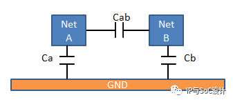
E.g:
C1 NetA NetB 2fF.
Decoupled Mode:
Net to net Capacitance are lumped to ground. I am not saying that this cap will not be extracted but I am saying that this Cap is not going to be part of output netlist as a separate Cap value. This Cap will be the Part of Total Cap (Cap with respect to Ground). So in place of 1 Cap value between Net A and Net B, we will get 2 Cap value.
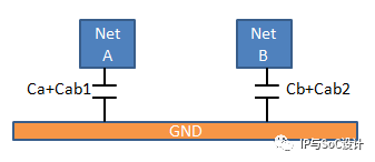
E.g :
C1 NetA GND 1.1fF
C2 NetB GND 0.9fF.
Capacitive coupling effects are not there in this mode. So You can't use such netlist during the SI analysis. It's comparatively less accurate but it can speed up simulation time a lot.
Just trying to explain the same with one more example.
There are 3 Net. "NetA, NetB, NetC". Different Capacitances are:
NetA -> NetB : 3fF
NetA -> NetC : 3fF
NetA -> GND : 8fF
NetB -> GND : 8fF
NetC -> GND : 8fF
Here NetB and NetC are far away, so not added the Coupling between them. All Nets are of Same Type, so you can see the Same CAP value.
When you extract the Capacitance in the Coupled Mode, Following is the Netlist.
C1 NetA NetB 3fF
C2 NetA NetC 3fF
C3 NetA GND 8fF
C4 NetB GND 8fF
C5 NetC GND 8fF
When you extract the Capacitance in the De-Coupled Mode, Following is the Netlist.
C1 NetA GND 11fF
C2 NetB GND 9.5fF
C3 NetC GND 9.5fF
What happen? Are you not able to figure out ?
CAP between NetA and NetB divided into 2 (here I am doing with equal part but it depends on Wire property and distance with Ground and all) 1.5fF each. Now this 1.5fF is added to NetB to Ground and NetC to Ground.
So value become 8 + 1.5fF = 11.5fF For Both NetB and NetC.
For Net A , it become 8 + 1.5fF (from NetB) + 1.5fF (from NetC) = 11fF.
If any content of this article infringes, please contact us to remove this article.
本文内容仅代表作者观点,不代表平台观点。
如有任何异议,欢迎联系我们。
如有侵权,请联系删除。

新闻来源:IP与SoC设计,文中所述为作者独立观点,不代表icspec立场。更多精彩资讯请下载icspec App。如对本稿件有异议,请联系微信客服specltkj。