


最近支持一个客户,需要在LPC5516下实现ADC 2Msps高速采集,根据数据手册描述:
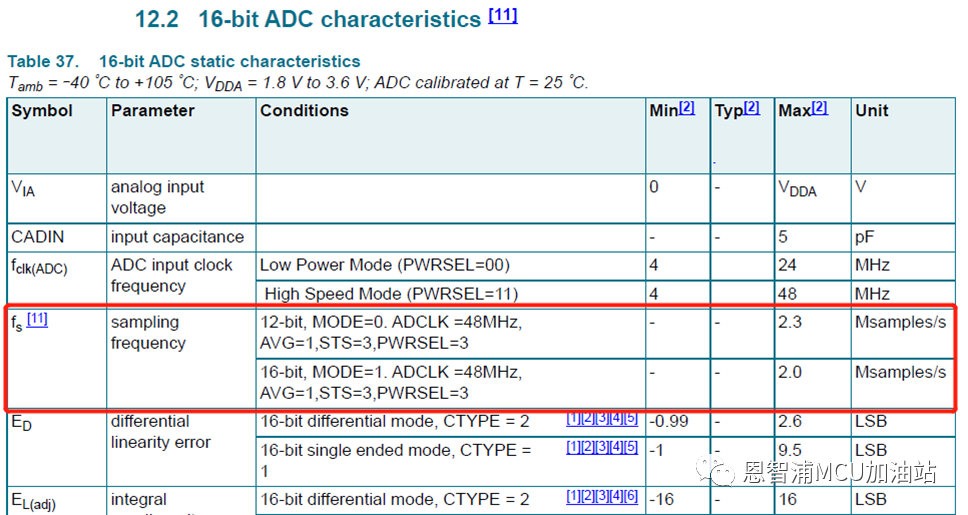
ADC在12-bit模式下最高可以达到2.3Msps
ADC在16-bit模式下最高可以达到2.0Msps.
那么实际情况是否真如数据手册所述,能达到如此高的转换速率呢?小编这次就编写了测试代码进行了实测,结果为:
12-bit模式下ADC最快可达2.326Msps, 16-bit模式下2.083Msps, 结果还是和数据手册很吻合的。
代码设计
代码基于SDK的例程:
\SDK_2_12_0_LPCXpresso55S16\boards\lpcxpresso55s16\driver_examples\lpadc\dma
修改:
1. 为了实现最快速度ADC采集,我们需要将ADC配置为:
ADC输入时钟: ADCCLK = 48MHz
无硬件平均: HWAVG=1
ADC采样时长设置为最短3xCLK: STS=0
ADC功率最大: PWRSEL=3
除此之外,还需要将ADC设置为连续转换模式:即将g_LpadcCommandConfigStruct.chainedNextCommandNumber指向自己,即完成当前转换后,自动开始下次转换。
以上所有配置对应SDK代码如下:
/* Configure ADC. */
LPADC_GetDefaultConfig(lpadcConfigStruct);
lpadcConfigStruct.enableAnalogPreliminary = true;
lpadcConfigStruct.conversionAverageMode = kLPADC_ConversionAverage1;
lpadcConfigStruct.powerLevelMode=kLPADC_PowerLevelAlt4;
lpadcConfigStruct.referenceVoltageSource = DEMO_LPADC_VREF_SOURCE;
lpadcConfigStruct.FIFO0Watermark = 2;
LPADC_GetDefaultConvCommandConfig(g_LpadcCommandConfigStruct);
g_LpadcCommandConfigStruct.channelNumber = DEMO_LPADC_USER_CHANNEL;
g_LpadcCommandConfigStruct.sampleTimeMode = kLPADC_SampleTimeADCK3;
g_LpadcCommandConfigStruct.loopCount = 1;
g_LpadcCommandConfigStruct.conversionResolutionMode = kLPADC_ConversionResolutionHigh;
//g_LpadcCommandConfigStruct.conversionResolutionMode =kLPADC_ConversionResolutionStandard;
g_LpadcCommandConfigStruct.chainedNextCommandNumber = DEMO_LPADC_USER_CMDID;
2. 配置DMA,使用DMA Ping-Pang buffer接收ADC数据,即定义两个DMA描述符,A和B:A传输完成后自动触发B,B传输完成后自动触发A。对应SDK代码为:
1.SDK_ALIGN(uint32_t s_dma_table[DMA_DESCRIPTOR_NUM * sizeof(dma_descriptor_t)], FSL_FEATURE_DMA_LINK_DESCRIPTOR_ALIGN_SIZE);
2.
3. const uint32_t g_XferConfig =
4. DMA_CHANNEL_XFER(true, /* Reload linkdescriptor after current exhaust, */
5. true, /* Clear trigger status.*/
6. true, /* Enable interruptA. */
7. false, /* Not enable interruptB. */
8. sizeof(uint32_t), /* Dma transfer width. */
9. kDMA_AddressInterleave0xWidth, /* Dma source address no interleave*/
10. kDMA_AddressInterleave1xWidth, /* Dma destination address nointerleave */
11. sizeof(uint32_t)*ADC_DMA_SIZE /* Dma transfer byte. */
12. );
static void DMA_Configuration(void)
{
dma_channel_config_t dmaChannelConfigStruct;
#if defined (DEMO_DMA_HARDWARE_TRIGGER) DEMO_DMA_HARDWARE_TRIGGER
/* Configure INPUTMUX. */
INPUTMUX_Init(DEMO_INPUTMUX_BASE);
INPUTMUX_AttachSignal(DEMO_INPUTMUX_BASE, DEMO_DMA_ADC_CHANNEL, DEMO_DMA_ADC_CONNECTION);
#endif /* DEMO_DMA_HARDWARE_TRIGGER */
/* Configure DMA. */
DMA_Init(DEMO_DMA_BASE);
DMA_EnableChannel(DEMO_DMA_BASE, DEMO_DMA_ADC_CHANNEL);
DMA_CreateHandle(g_DmaHandleStruct, DEMO_DMA_BASE, DEMO_DMA_ADC_CHANNEL);
DMA_SetCallback(g_DmaHandleStruct, DEMO_DMA_Callback, NULL);
/* Prepare and submitthe transfer. */
DMA_PrepareChannelTransfer(dmaChannelConfigStruct, /* DMA channel transfer configuration structure. */
(void *)DEMO_LPADC_RESFIFO_REG_ADDR, /* DMA transfer source address.*/
(void *)adc_result, /* DMA transfer destination address. */
g_XferConfig, /* Xfer configuration */
kDMA_PeripheralToMemory, /* DMAtransfer type. */
NULL, /*DMA channel trigger configurations. */
(dma_descriptor_t *)(s_dma_table[0]) /* Address of next descriptor. */
);
DMA_SubmitChannelTransfer(g_DmaHandleStruct, dmaChannelConfigStruct);
/* Set two DMAdescripters to use ping-pong mode. */
DMA_SetupDescriptor((dma_descriptor_t *)(s_dma_table[0]), g_XferConfig, (void *)DEMO_LPADC_RESFIFO_REG_ADDR, (void *)adc_result, (dma_descriptor_t *)(s_dma_table[4]));
DMA_SetupDescriptor((dma_descriptor_t *)(s_dma_table[4]), g_XferConfig, (void *)DEMO_LPADC_RESFIFO_REG_ADDR, (void *)adc_result, (dma_descriptor_t *)(s_dma_table[0]));
}
3. 最后小编还使能了SysTick定时器用于记录转换时间,程序开始运行后,ADC会启动连续转换,DMA设置为传输100次ADC转换结果后触发DMA完成中断, DMA中断触发后(传输完成),程序会统计ADC转换时间,计算ADC转换结果的平均值和标准差,以及打印转换结果。
代码清单
最后为大家呈上完整代码清单(可以直接复制到lpadc_dma.c里运行):
下期,将重点聊聊影响ADC转换误差的各种因素。
恩智浦MCU加油站
这是由恩智浦官方运营的公众号,着重为您推荐恩智浦MCU的产品信息、开发技巧、教程文档、培训课程等内容。

长按二维码,关注我们
END
更多恩智浦AI-IoT市场和产品信息,邀您同时关注“NXP客栈”微信公众号

NXP客栈
恩智浦致力于打造安全的连接和基础设施解决方案,为智慧生活保驾护航。
长按二维码,关注我们